

Standard electrical sample mounting options are detailed below:
| Electrical Sample Mounts | ||||
|---|---|---|---|---|
| Option | CC16 | R2D12 | RF4 | 6 | 8 | MO14 |
 |
 |
 |
 |
|
| Description | cryogenic optimized chip carrier with DIP16 compatibility | circuit board with electrical contact pads and coax connections | coax waveguide sample PCB with GSG bonding pads | wire bonding pads on narrow circuit board with pitch connector |
| Low Voltage Connections | 16 DC (8 or 12 by request) |
12 DC | n/a | 14 DC |
| High Frequency Connections | n/a | 2 RF coax | 2, 4, or 8 RF coax | n/a |
| Width | 19mm | 24mm | depends on configuration | 5.5mm narrowest |
| Required Space* | 21mm | 26mm | depends on configuration | 7.5mm |
| Customizable | Alternate pad sizes available | Alternate # of DC & RF lines possible | Alternate # of RF lines possible | Yes |
| Configurations | Fixed mount, nanopositioner mount, or ATSM with exchange boss | Fixed mount or nanopositioner mount | Fixed mount, nanopositioner mount, or ATSM with exchange boss | Parallel, normal, or 45° to lateral |
| Best For | quick sample changes & low working distance | coplanar waveguides, microwave excitation, & low signal level experiments | use with Magneto-Opticmodule | |
*Electrical sample mounts should have at least 1mm of spacing on either side.
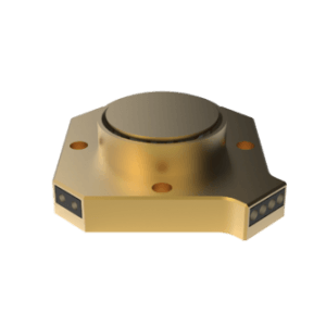
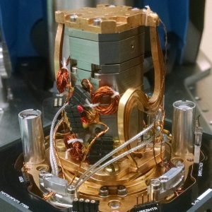
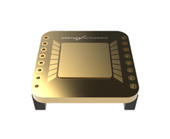
CC16 ELECTRICAL SAMPLE MOUNT
The CryoChip16 (CC16) has 16 low frequency DC gold plated wire bonding pads on a cryogenic optimized sample mount. The cold sample mounting surface is raised slightly above the PCB, and the exchange boss connection provides an excellent thermal path between the platform and sample. The exchange boss design facilitates quick change between setups and is compatible with exchange boss mounts for nanopositioners or the ATSM. An optional thermometer can also be mounted directly below the sample mounting surface for accurate temperature readouts.
 |
 |
 |
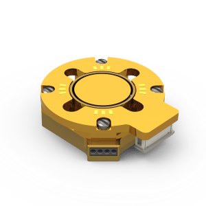
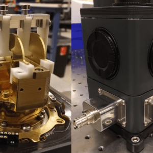
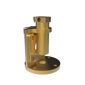
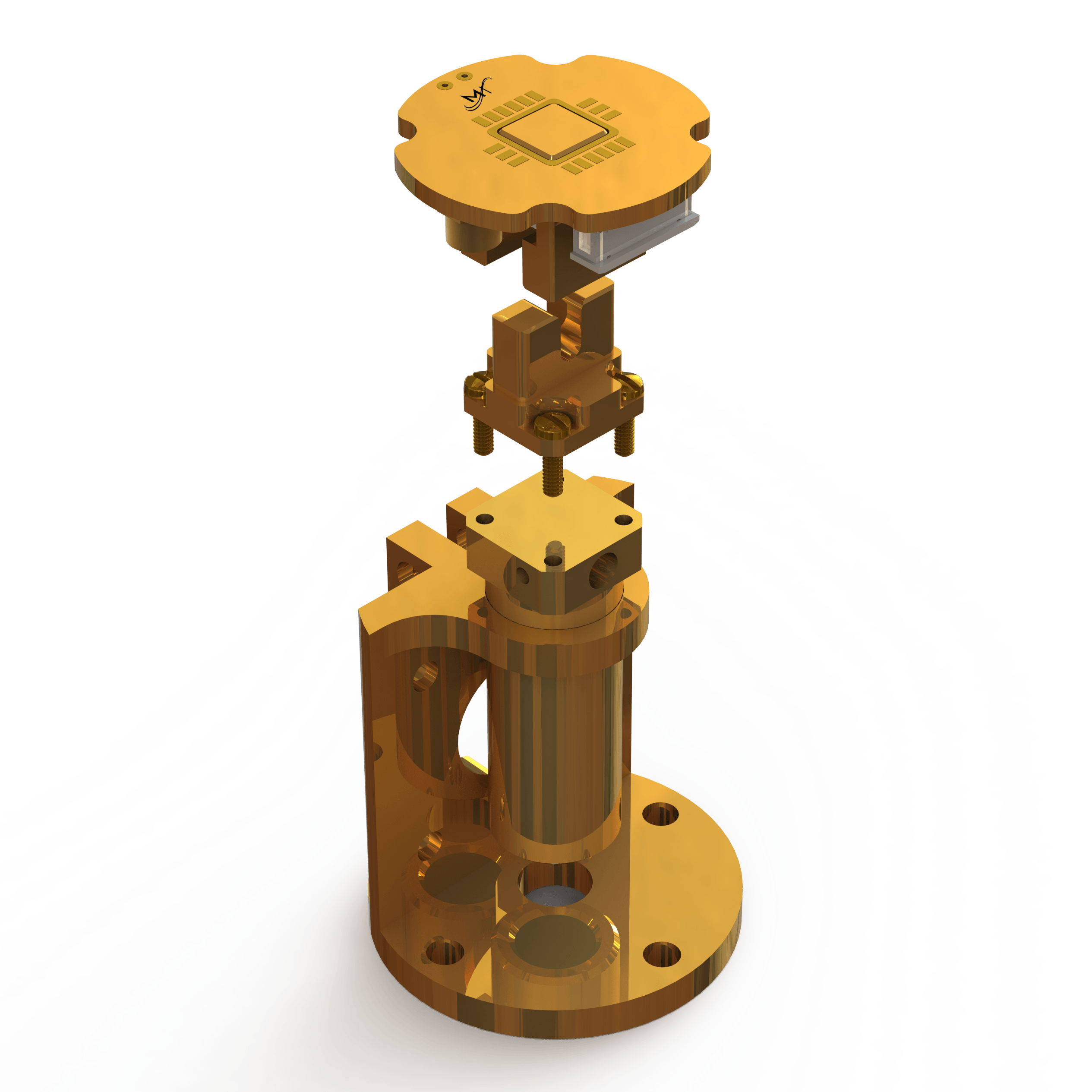
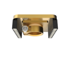
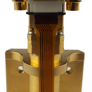
R2D12 ELECTRICAL SAMPLE MOUNT
The R2D12 has 12 low frequency DC connectors along with 2 high frequency RF (coax) connectors on a small circuit board. The chip carrier is easily removed from the cryostat sample mount, providing a convenient platform for wire bonding or soldering electrical connections between the user’s device and the chip carrier. The 12 wire bonding pads connect via ribbon flex circuits which provide superior thermal anchoring and keep the wiring clean and organized.
 |
 |
 |
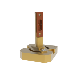
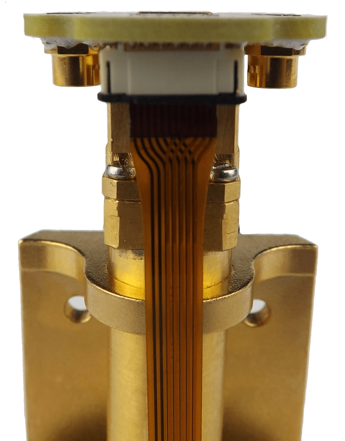
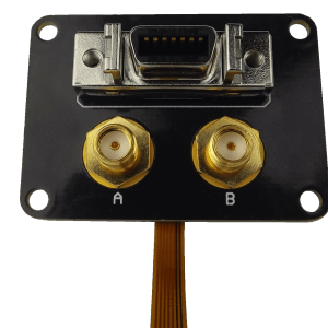
The ribbon flex circuit connects the wire bonding pads (left/center) to the exterior base side panel (right).
The 2 RF bonding pads are great for coplanar waveguide studies. The signal remains shielded all the way to the device under study, ensuring a lower loss of signal. An internal copper shielding layer shields the DC lines from the RF coax to prevent signal distortion, enabling both high voltage experiments and sensitive, low signal level experiments.
 |
 |
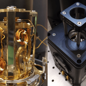
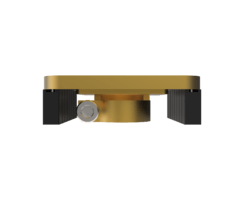
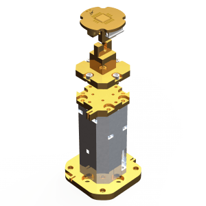
The R2D12 can be mounted on the standard thermally damped sample mount (left) or on a fixed mount for use on piezo positioners (right).
The sample chip is surrounded by a ground layer for additional electromagnetic shielding. The sample surface sits above the PCB height to allow for low working distance. The grounding scheme can be reconfigured by the user per their experimental requirements, and the number and type of contacts can be customized by Montana Instruments upon request.
RF4 | 6 | 8 COAX SAMPLE MOUNT
The RF4 sample mount has 4 high frequency RF connections on a coax waveguide sample PCB with ground-signal-ground (GSG) bonding pads. The mount leverages the exchange boss connection style for optimized thermal performance, quick exchange between setups, and compatibility with exchange boss mounts, including options for nanopositioners or the ATSM. Alternative 6 RF or 8 RF designs are also available.
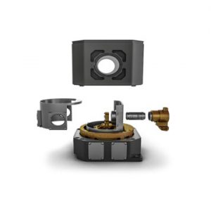
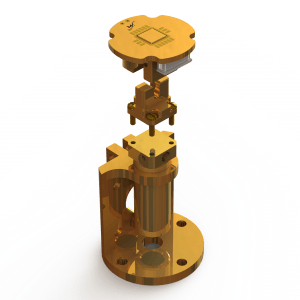
MO14 ELECTRICAL SAMPLE MOUNT
The MO14 circuit board is designed for positioning samples with electrical connections within the magnetic field of the Magneto-Optical system. The circuit board offers 14 pads for wire bonding and a 1mm pitch connector at the bottom to cable the board to the measurement devices outside the cryostat. The board has space for a 3mm wide sample which works well with the pole tip spacing of 12mm for a 0.7 Tesla field. A radiation shield at the sample temperature may be installed above the sample.
The sample pad ensures a cold sample. Once the sample is mounted and electrically connected, the sample pad may be permanently fastened to the electrical contact board. Multiple assemblies may be used for multiple samples. Mounts are available to position the board at angles with respect to the field and optical axes.
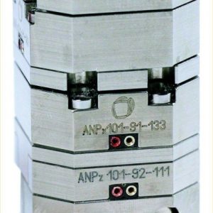
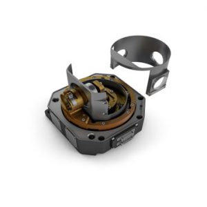
Often users want to investigate their samples in the Faraday and Voigt geometries. The user can position their sample parallel or normal to the lateral magnetic field. Alternatively, the assembly may be mounted on a rotary piezo stack with a vertical axis and thus rotated while at cryogenic temperatures.
 |
 |
A narrow option is also available (shown below) which can be mounted at 45 degrees for reflection measurements.
 |
 |
 |